Introduction
Dry Film Thickness (DFT) refers to the thickness of a coating once it has dried and fully cured on a substrate. In any anticorrosive coating system, the coating plays a crucial role. Its primary function is to prevent corrosion by adhering firmly to the substrate. To achieve effective protection and ensure proper adhesion, it is essential that the coating is applied at the appropriate thickness. But how do we measure the thickness of the coating and ensure its compliance with the industry standards? Read on to know everything about dry film coating thickness, how it is measured, equipment used and its working principles, and the acceptance criteria for dry film coatings.
What is Dry Film Thickness?
Dry film thickness (DFT) refers to the measured thickness of a coating applied over a substrate. It may comprise a single layer or multiple layers and is assessed once the coating has fully cured. It is typically measured in micrometers (µm) or mils (1 mil = 25.4 µm). DFT is a critical quality control parameter that directly influences the performance, durability, and protective properties of coatings in various industrial applications.
Coating thickness is measured using two primary tools: a wet film thickness (WFT) gauge and a dry film thickness (DFT) gauge. A WFT gauge is designed to assess the thickness of a wet coating while it is still in liquid form. It must be used during application to obtain an accurate reading before significant solvent evaporation occurs. For precise dry film measurements, a DFT gauge is employed only after the coating has reached thumbprint hardness, ensuring reliable and accurate results.
Measuring film thickness is necessary to confirm compliance with standards such as ASTM, ISO, and other industry specifications. Measuring dry film thickness (DFT) is essential, even in the most basic protective coating specifications, as it is a key factor in determining the durability of a coating system. The thickness of each individual coating layer, as well as the total system DFT, must be assessed and documented to confirm that the applied system meets the required durability standards.
Key Terms and Definitions
- Dry-film thickness (DFT): Thickness of a coating above the peaks of a rough surface.
- Nominal Dry Film Thickness (NDFT): The specified thickness of a coating to ensure durability.
- Correction Value: A factor subtracted from readings to account for surface roughness effects.
- Sampling Plan: Defines the number of measurements required in an inspection area.

DFT measurements must also comply with established standards, which include proper gauge calibration and consideration of surface profile effects on thickness readings. The number of measurement points required varies depending on the size of the coated area. Let’s look at the important standards.
Standards & Guidelines for DFT Measurements
Various international standards govern DFT measurement to ensure consistency, accuracy, and compliance. They are as follows:
- SSPC-PA 2 (Steel Structures Painting Council – USA)
- Specifies the minimum and maximum allowable DFT for different coating systems.
- Defines spot measurement and area averaging techniques.
- ISO 19840 (International Standards Organization)
- Defines acceptance criteria for coatings on steel structures.
- Allows for different tolerances based on nominal thickness.
- ASTM D7091 (American Society for Testing and Materials)
- Provides guidelines for measuring coatings on metallic substrates by Magnetic and Eddy Current Gauges.
- NACE SP0188 (National Association of Corrosion Engineers)
- Covers procedures for DFT verification.
Standard | Description | Applicability |
ISO 19840 | Defines DFT measurement procedures on rough surfaces and acceptance criteria. | Structural steel, marine, oil & gas |
SSPC-PA 2 | Provides a standardized method for verifying DFT compliance using magnetic gauges. | Protective coatings in steel structures |
ASTM D7091 | Defines procedures for using electronic gauges to measure DFT on metallic substrates. | Industrial applications, oil & gas |
NACE SP0188 | Covers coating thickness measurement for corrosion control in various environments. | Pipelines, offshore platforms |
Measuring Dry Film Coating Thickness
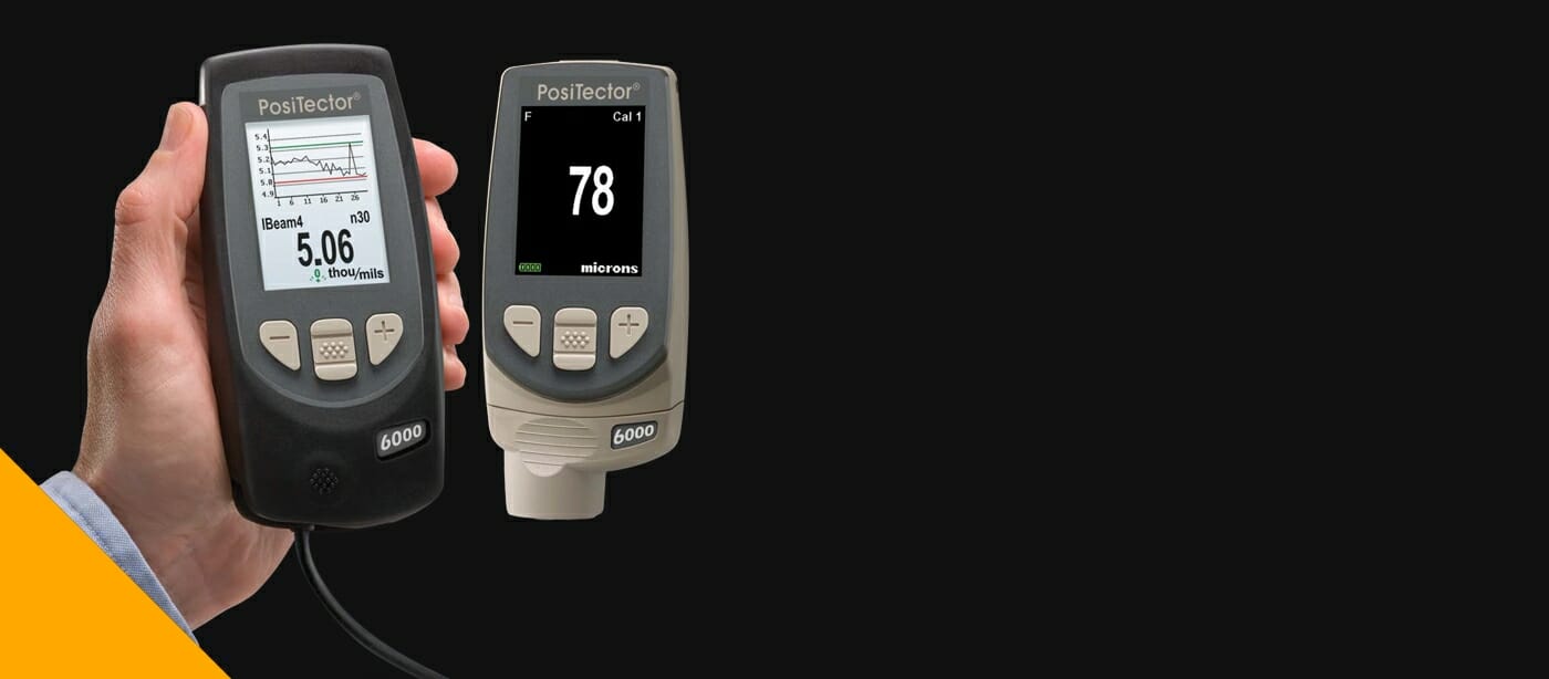
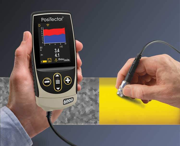
A standard dry film thickness (DFT) test is conducted using either a handheld or remote-operated DFT measurement gauge to assess the coated surface. The choice of gauge depends on the substrate material and coating type, with options including magnetic induction, electromagnetic, eddy current, or ultrasonic gauges.
Electronic DFT gauges are the most widely used due to their ease of operation, versatility, and high measurement accuracy. Modern models come equipped with a magnetic induction mode for measuring coatings on ferrous metals (e.g., steel) and an eddy current mode for coatings applied to non-ferrous metals like aluminum. Before we delve deeper into the different types of DFT gauges, let’s look at the working principles of these gauges.
Principles of Measurement Methods for Dry Film Coating Thickness
Accurately measuring coating thickness is essential in various industrial applications to ensure compliance with quality and performance standards. Different measurement principles are used depending on the substrate type and the specific coating requirements. The following sections describe the most applied principles in dry film thickness (DFT) measurement.
Permanent-Magnet Principle
The permanent-magnet method relies on the interaction between a static magnetic field and a magnetic substrate to determine coating thickness. These instruments work by measuring the magnetic field strength between a permanent magnet and the coated surface. Since the strength of the magnetic field changes based on the distance between the magnet and the substrate, the instrument is able to correlate this variation to the coating thickness. This method is widely used for coatings applied to ferrous materials, such as steel.
Pull-Off Permanent-Magnet Principle
The pull-off permanent-magnet method operates similarly to the permanent-magnet principle but differs in its approach to measurement. Instead of directly assessing magnetic field strength, this method measures the force required to detach a magnet from the coated surface. The level of force needed to overcome the magnetic attraction is directly proportional to the thickness of the coating. This technique is particularly useful for coatings applied to ferrous substrates where a non-destructive, reliable thickness measurement is required.
Magnetic-Induction Principle
The magnetic-induction method employs an electronic probe to generate a magnetic field using either a permanent magnet with a Hall sensor or an electromagnet with an induction coil. The thickness of the coating is determined by analyzing the changes in magnetic field strength as the probe interacts with the underlying magnetic substrate. Since the presence of a coating alters the distance between the probe and the substrate, the instrument calculates the thickness based on the resulting variation in magnetic flux density. This technique is highly effective for ferrous metal coatings and is widely used in industries requiring precision measurement.
Eddy Current Principle
The eddy current method is primarily used for measuring coating thickness on non-magnetic metal substrates, such as aluminum and copper. As the probe nears the coated surface, it induces eddy currents in the conductive substrate. The strength and characteristics of these eddy currents vary based on the thickness of the non-conductive coating, allowing the instrument to calculate the coating’s exact thickness. This method is particularly valuable in applications where coatings are applied to non-ferrous metals.
Each of these measurement principles offers unique advantages and is chosen based on substrate type, coating material, and required measurement precision. Now, let’s move on to the different types of instruments used for the measurement of dry film thickness in coatings.
Choosing the Right DFT Gauge
Dry film thickness (DFT) measurement tools and techniques fall into two main categories: destructive and non-destructive methods.
Destructive DFT measurement techniques, such as cross-sectional microscopy and microgravimetric analysis, require removing or damaging the coating to assess its thickness. While these methods provide highly precise measurements, they are not suitable for assets that remain in service.
Non-destructive testing (NDT) methods are more commonly used in asset management because they allow for thickness measurement without compromising the integrity of the coating. Magnetic induction and eddy current gauges enable you to determine DFT without causing structural damage. These methods deliver instant results, making them ideal for routine inspections and quality control.
The following section explores the most commonly used dry film thickness gauges for both NDT and destructive testing.
Mechanical Coating Thickness Gauges
Mechanical coating thickness gauges are traditional yet reliable tools for measuring coating thickness. One well-known example is the Elcometer 211, often referred to as the “banana gauge” due to its distinctive curved shape and yellow color. This device operates using a dial gauge system, where a spring-loaded pin or probe deflects to determine the coating’s thickness. It is capable of measuring non-magnetic coatings—such as paint, powder coating, plastic, and epoxy—up to 6 mm (250 mils) with an accuracy margin of less than 5%.
Another widely used mechanical gauge is the MikroTest from Erichsen, which employs the magnetic holding force method to measure the thickness of non-magnetic coatings (such as paint, lacquer, rubber, plastic, and galvanic coatings) on steel substrates. These gauges provide dependable readings without requiring a power source, making them an excellent choice for field inspections and industrial applications.
Advantages and Limitations of Mechanical DFT Gauges
Mechanical dry film thickness (DFT) gauges are portable, cost-effective, and simple to use. They can be employed on a variety of surfaces, including organic materials like wood. Since they lack electronic components, these gauges are ideal for use in high-temperature environments or areas with strong electromagnetic interference (EMI), where electronic devices might malfunction.
However, mechanical gauges have certain limitations. Their measurement precision is lower compared to electronic alternatives, and accuracy largely depends on the inspector’s skill. Additionally, the process is more time-consuming, as these devices do not feature automatic calibration, data logging, or built-in analytics. Due to these drawbacks, most inspection teams prefer electronic DFT gauges, which offer greater efficiency and reliability.
Magnetic Induction and Eddy Current DFT Gauges
Modern electronic dry film thickness (DFT) gauges are designed with dual measurement capabilities, allowing them to operate in two distinct modes:
- Magnetic Induction Mode: This method determines coating thickness by generating a magnetic attraction between the probe and the metal substrate. It then measures variations in magnetic flux to calculate the coating thickness. This technique is specifically used for ferrous materials such as steel.
- Eddy Current Mode: This technique relies on analyzing induced eddy currents as the probe approaches the coated surface. By assessing changes in the electromagnetic response, it accurately measures non-conductive coatings applied to non-ferromagnetic substrates, such as aluminum or stainless steel.
Ultrasonic DFT Gauges
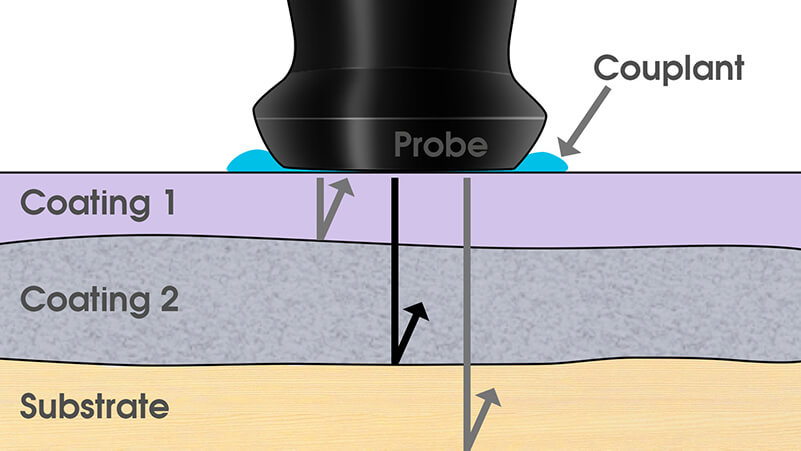
Ultrasonic testing is one of the most versatile methods for measuring coating thickness, as it can be applied to virtually any material, including metals, alloys, plastics, and wood.
This technique works by analyzing sound wave propagation and reflection within the test material. It applies a straightforward calculation i.e., the speed of sound is multiplied by the time of flight of a high-frequency sound wave, and the result is divided by two to determine thickness.
Advanced ultrasonic DFT gauges are capable of accurately measuring individual layers within a multi-layer coating system, making them particularly useful for complex industrial coatings.
Hall Effect Gauge
As the name suggests, a Hall effect gauge operates based on the Hall effect principle, which detects variations in magnetic fields to measure coating thickness. When positioned near a surface, the gauge measures changes in magnetic flux density, allowing for precise thickness determination.
Unlike other DFT measurement tools, the Hall effect gauge is compatible with a wide range of materials, including plastics, non-ferrous metals, glass, wood, and certain non-magnetic stainless steel alloys. This versatility makes it a preferred choice for quality control in manufacturing. One notable application is inspecting airbag tear seams on molded plastic containers, ensuring consistency and reliability in production processes.
Before conducting the test, it is essential to calibrate the dry film thickness (DFT) gauge properly to ensure accurate measurements. Let’s move on to how a DFT gauge is calibrated.
Calibrating a Coating Dry Film Thickness Gauge: A Step-by-Step Guide
Like many precision instruments used for quality assessment, a coating thickness gauge has a built-in error tolerance. Regular calibration is essential to ensure the device remains within acceptable accuracy limits. Periodic verification helps confirm that the instrument has not exceeded its tolerance range, maintaining reliable and consistent readings.
Steps to Calibrate a Coating Thickness Gauge
- Establish a Zero Reference
- Take 5 to 10 measurements on an uncoated substrate to determine the zero reference point.
- Set the Calibration Foil
- Place a calibration foil on the uncoated surface and take another 5 to 10 measurements.
- The recorded values should closely match the nominal thickness of the foil.
- Verify Accuracy
- The closer the measured values are to the actual coating thickness, the more accurate the gauge calibration.
- If discrepancies arise, repeat the calibration process or adjust the instrument settings as needed.
Regular calibration ensures accurate and repeatable measurements, making it a crucial step in quality control and coating inspection procedures. Also, before you begin testing, make sure you:
- Select the correct probe based on whether you are measuring DFT on a ferrous or non-ferrous
- Calibrate and verify the gauge, ideally with the supplier, at least once a year.
- Clean and inspect the probe tip, ensuring it is in good condition for accurate readings.
- Perform zero calibration and adjust the gauge using an appropriate thickness shim.
- Clean the coated surface, removing any debris that could interfere with measurements.
- Ensure the metal substrate is at ambient temperature before taking readings to avoid inaccuracies.
- Position the probe perpendicular to the surface for precise and reliable measurement results.
Procedure for measuring the Dry Film Coating Thickness
Accurate dry film thickness (DFT) measurement is critical for ensuring coating performance, compliance with industry standards, and long-term asset protection. Here’s a detailed guide on the procedure for measuring the dry film thickness. Let’s begin with the sampling plan:
Sampling Plan for Dry Film Thickness (DFT) Measurement
A well-defined sampling plan determines the number of measurement points required within a designated inspection area. If a structure has not been segmented into specific inspection zones, the entire structure is considered as the inspection area for DFT assessment. Adhering to a systematic measurement approach ensures that coating application meets the minimum thickness requirements specified in relevant standards, such as ISO 12944-7 and ISO 12944-8.
Inspection areas are typically outlined in the project specifications, providing clear guidance on where measurements should be taken. However, special consideration must be given to complex structural features that may pose challenges in coating application and measurement accuracy. Areas requiring additional inspection include:
- Welds and welded joints
- Edges and corners
- Fixtures and fasteners
- Brackets, stiffeners, and supports
- Attached piping and inaccessible zones
- Regions exhibiting surface defects or irregularities
Since these areas often experience variable coating thickness due to application challenges, supplementary random measurements must be conducted in accordance with established sampling requirements.
Minimum Measurement Requirements for DFT
The minimum number of DFT measurements required for verification depends on the total size and complexity of the inspection area. The table given below provides guidelines for determining the necessary representative sample size i.e., the minimum number of measurements for Dry Film Thickness (DFT) verification.
Inspection Area (m² or m) | Minimum Number of Measurements | Maximum Number of Measurements Allowed to be Repeated |
Up to 1 | 5 | 1 |
Above 1 to 3 | 10 | 2 |
Above 3 to 10 | 15 | 3 |
Above 10 to 30 | 20 | 4 |
Above 30 to 100 | 30 | 6 |
Above 100a | Add 10 for every additional 100 m² or 100 m (or part thereof) | 20% of the minimum number of measurements |
During a series of DFT measurements, if an individual reading falls outside the acceptable range, a corrective remeasurement must be performed to verify the accuracy of the initial reading.
Corrective Re-Measurement Process
When a measurement fails to meet the specified criterion, the following steps must be undertaken:
- Repeat the Measurement
- A new measurement should be taken within 10 mm of the original test location to ensure consistency.
- Reject the Initial Value
- If the repeated measurement yields a value within the acceptable tolerance, it replaces the original measurement.
- Record the New Value
- The updated measurement becomes the official DFT reading for that point.
- If the second measurement also fails to meet the required criterion, it shall not be replaced, and the deviation must be documented accordingly.
Correction Values for Surface Profile in DFT Measurement
Accurate dry film thickness (DFT) measurement requires adjusting for substrate roughness, especially on abrasive blast-cleaned surfaces. If the surface profile conforms to ISO 8503-1, the following correction values apply:
Surface Profile (ISO 8503-1) | Correction Value (µm) |
Fine | 10 |
Medium | 25 |
Coarse | 40 |
If the surface profile is unknown and no uncoated sample is available, a default correction value of 25 µm is used. When applied, the correction value is subtracted from the individual DFT reading to ensure accurate coating thickness assessment.
Acceptance Criteria for Dry Film Thickness (DFT) as per ISO 19840-2012
The acceptance of an inspection area is determined based on a set of standardized criteria as per ISO 19840-2012 that ensure the coating thickness is within the required range. The following conditions must be met for an inspection area to be deemed compliant:
- Mean DFT Compliance
- The arithmetic mean of all individual DFT measurements must be equal to or greater than the nominal dry film thickness (NDFT) specified in the coating system requirements.
- Minimum Thickness Requirement
- Each individual DFT measurement must be at least 80% of the NDFT to ensure adequate coating coverage and performance.
- Allowable Tolerance Range
- Individual readings between 80% and 100% of the NDFT are acceptable, provided that these measurements do not exceed 20% of the total number of readings taken within the inspection area. This ensures localized variations remain within permissible limits.
- Maximum Dry Film Thickness Compliance
- No individual DFT measurement shall exceed the specified maximum dry film thickness. If a maximum DFT value is not explicitly stated, guidance should be obtained from ISO 12944-5, which provides recommendations for coating thickness limitations in protective paint systems.
Conclusion
Dry film thickness (DFT) measurement is a critical quality control parameter in protective coatings, ensuring corrosion resistance, durability, and compliance with industry standards. Accurate DFT assessment involves using appropriate measurement techniques, calibrated instruments, and standardized sampling plans to verify coating integrity. Advanced measurement technologies, including magnetic induction, eddy current, ultrasonic, and Hall effect gauges, allow for precise and reliable evaluations.
Ultimately, adhering to proper measurement procedures, correction values for surface roughness, and acceptance criteria enhances the performance, longevity, and effectiveness of protective coating systems.
References
- https://voliro.com/blog/dry-film-thickness-measurement/
- https://www.iso.org/obp/ui/en/#iso:std:iso:19840:ed-2:v1:en
- https://www.astm.org/d5796-20.html
- ISO 19840-2012
- DEFELSKO USA


